Snap Fin
[07/05/2010]
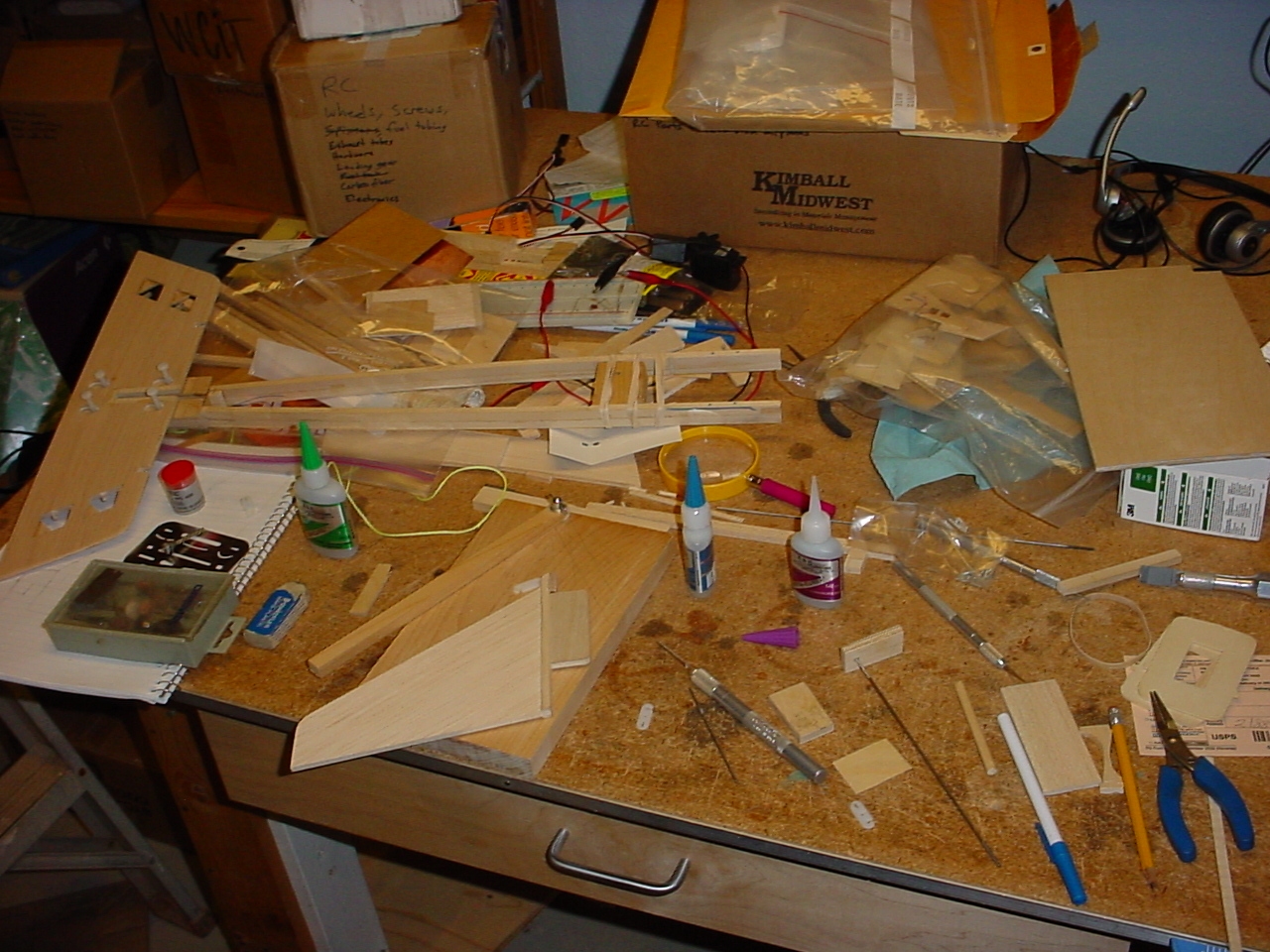 I was busy working on my airplane today. Can you tell? Can you find my work pieces among this mess?
I've got too much stuff scattered around, and for some reason, I can't seem to get into a groove with
my building processes - probably a sign that it has simply been too long - so the workbench became cluttered
rather quickly, and I found myself working with things on my lap. Not good. I even have another makeshift
temporary table, but it is almost just as cluttered, mostly with sanding blocks and raw materials (wood)
for building my plane. I intend on getting things a little more straightened out tomorrow.
I was busy working on my airplane today. Can you tell? Can you find my work pieces among this mess?
I've got too much stuff scattered around, and for some reason, I can't seem to get into a groove with
my building processes - probably a sign that it has simply been too long - so the workbench became cluttered
rather quickly, and I found myself working with things on my lap. Not good. I even have another makeshift
temporary table, but it is almost just as cluttered, mostly with sanding blocks and raw materials (wood)
for building my plane. I intend on getting things a little more straightened out tomorrow.
 After much planning and refinement of my checklist, I jumped completely into improv mode today and flew
completely by the seat of my pants. The mechanism for securing the fin in place has bothered me for a
long time now, and I took it upon myself to resolve the issue once and for all. But first, everything
hinged on fixing a mistake I made a while back with the placement of the electrical connector in the tail.
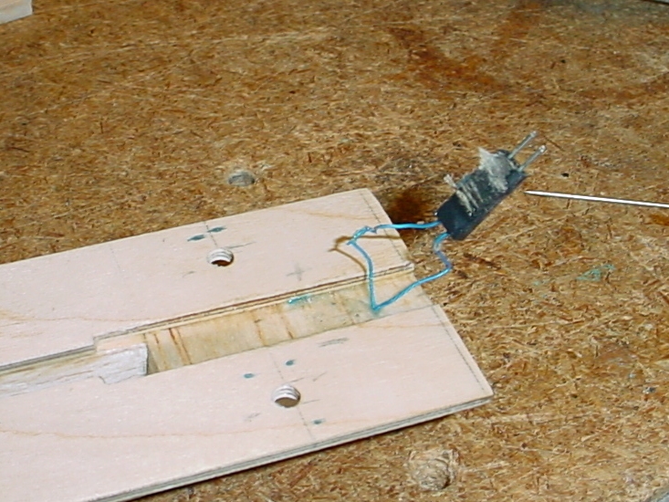
So, my first order of business was to correct this flaw. I started by soaking the piece in question in
CA glue remover. It took quite a while before the connector came loose, and some of the enamel came off
one of the wires in the process, but I finally got it to come up. This picture is deceiving, however,
as I made two failed attempts to reposition the connector, so this picture basically shows the results
of pulling this connector up for the third time!
After much planning and refinement of my checklist, I jumped completely into improv mode today and flew
completely by the seat of my pants. The mechanism for securing the fin in place has bothered me for a
long time now, and I took it upon myself to resolve the issue once and for all. But first, everything
hinged on fixing a mistake I made a while back with the placement of the electrical connector in the tail.
So, my first order of business was to correct this flaw. I started by soaking the piece in question in
CA glue remover. It took quite a while before the connector came loose, and some of the enamel came off
one of the wires in the process, but I finally got it to come up. This picture is deceiving, however,
as I made two failed attempts to reposition the connector, so this picture basically shows the results
of pulling this connector up for the third time!
 Needless to say, I was extremely frustrated. But then I figured out a way to ensure that the connector
would remain in alignment - by shimming up the sides with some steel pushrods that were just the right
size - and I was successful from there. This series of images are not the greatest quality, but you
get the idea. I got the connector to sit in the proper place, in perfect alignment with the mating
connector on the stabilizer, and then it was simply a matter of laying the wires down flat. Then, to
protect them, I cut out and placed some balsa caps over top, where they will be forever entombed. No
wire chafing will occur here! This whole connector fiasco was a pain in the butt and took way more time
than I anticipated. I also lied in the implication that this task was done today. I actually did this
on Saturday - two days ago. But this set the stage to allow me to continue with the work that I did do
today.
Needless to say, I was extremely frustrated. But then I figured out a way to ensure that the connector
would remain in alignment - by shimming up the sides with some steel pushrods that were just the right
size - and I was successful from there. This series of images are not the greatest quality, but you
get the idea. I got the connector to sit in the proper place, in perfect alignment with the mating
connector on the stabilizer, and then it was simply a matter of laying the wires down flat. Then, to
protect them, I cut out and placed some balsa caps over top, where they will be forever entombed. No
wire chafing will occur here! This whole connector fiasco was a pain in the butt and took way more time
than I anticipated. I also lied in the implication that this task was done today. I actually did this
on Saturday - two days ago. But this set the stage to allow me to continue with the work that I did do
today.
Today began with a long, drawn out thought session. In fact, most of my day was spent churning, just
trying to figure out how in the world I was going to make this thing work. One of the rules that I defined early
on in this project for the end product was driving me batty:
With the exception of the wing mounting bolts, no mounting pins or other apparatus may be completely detachable
from the airframe or require the use of tools to secure or detach.
 So, I struggled with this basically all day, and still have not completely resolved the issue, but I did make
some progress. The first step was to get an idea how much the gap for the fin was going to be affected by
paint. So, I cut out a couple small pieces, created a snug fit, then widened the gap a tiny bit and painted
and sealed the pieces. It probably wasn't the best test as I used balsa instead of the hardwood used on the
actual airframe, and painting it actually seemed to mysteriously loosen the spacing between everything, instead
of filling in the gaps as I would expect.
So, I struggled with this basically all day, and still have not completely resolved the issue, but I did make
some progress. The first step was to get an idea how much the gap for the fin was going to be affected by
paint. So, I cut out a couple small pieces, created a snug fit, then widened the gap a tiny bit and painted
and sealed the pieces. It probably wasn't the best test as I used balsa instead of the hardwood used on the
actual airframe, and painting it actually seemed to mysteriously loosen the spacing between everything, instead
of filling in the gaps as I would expect.
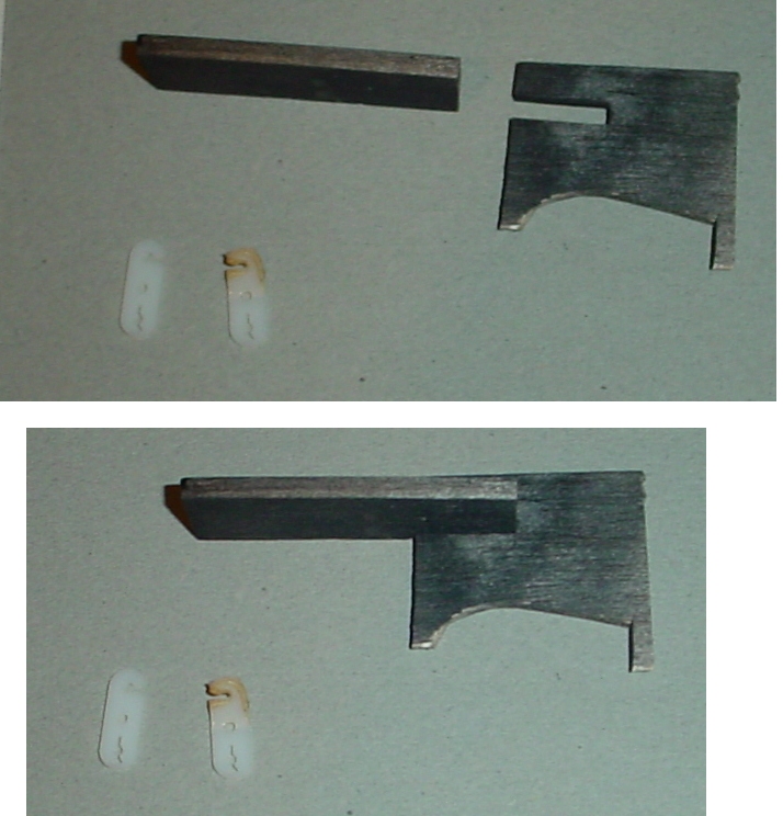
On an unrelated task, I could not find any of the right-angle hatch latches made by Carl Goldberg, but I did
find a set of very similar flat hold-downs. I had a design in mind for the right-angle ones, so I did an
experiment to see if I could bend the flat ones into a right angle. But this failed miserably, as you can
see the darkened one that I boiled under a propane torch (the heat gun wasn't hot enough).
 I sanded the fin slot a tiny bit to loosen the tolerance so the fin would basically drop in without any
effort. I took a bit of a risk by putting the tail under the chop saw to shave the very back end square.
Probably not the best idea in hindsight, but the results were very good. So then I decided to box it in.
I started with the lower gusset. Rather than use the template that
I cut out at the beginning of this project, I traced the tail boom onto a piece of plywood and cut that out.
I was not thinking ahead when I attached it, to make sure the tail boom was straight (i.e. not flexed
unevenly), as attaching this piece would make it difficult to adjust or correct if necessary. But I checked
the alignment later when the "oh crap" response prompted me to do so. It turned out that everything looks
good. The tail is right where it needs to be. I'm telling you, this thing wants to fly!
I sanded the fin slot a tiny bit to loosen the tolerance so the fin would basically drop in without any
effort. I took a bit of a risk by putting the tail under the chop saw to shave the very back end square.
Probably not the best idea in hindsight, but the results were very good. So then I decided to box it in.
I started with the lower gusset. Rather than use the template that
I cut out at the beginning of this project, I traced the tail boom onto a piece of plywood and cut that out.
I was not thinking ahead when I attached it, to make sure the tail boom was straight (i.e. not flexed
unevenly), as attaching this piece would make it difficult to adjust or correct if necessary. But I checked
the alignment later when the "oh crap" response prompted me to do so. It turned out that everything looks
good. The tail is right where it needs to be. I'm telling you, this thing wants to fly!
 Then I placed a cap over the face of the slot to complete the box. I couldn't decide whether to cut it
flush with the upper and lower plates or flush with the tail boom, but wound up cutting it flush with the
tail boom. This turned out to be the right thing to do as it gave a tiny bit more room that was needed
to implement the design that I had (roughly) in my head.
Then I placed a cap over the face of the slot to complete the box. I couldn't decide whether to cut it
flush with the upper and lower plates or flush with the tail boom, but wound up cutting it flush with the
tail boom. This turned out to be the right thing to do as it gave a tiny bit more room that was needed
to implement the design that I had (roughly) in my head.
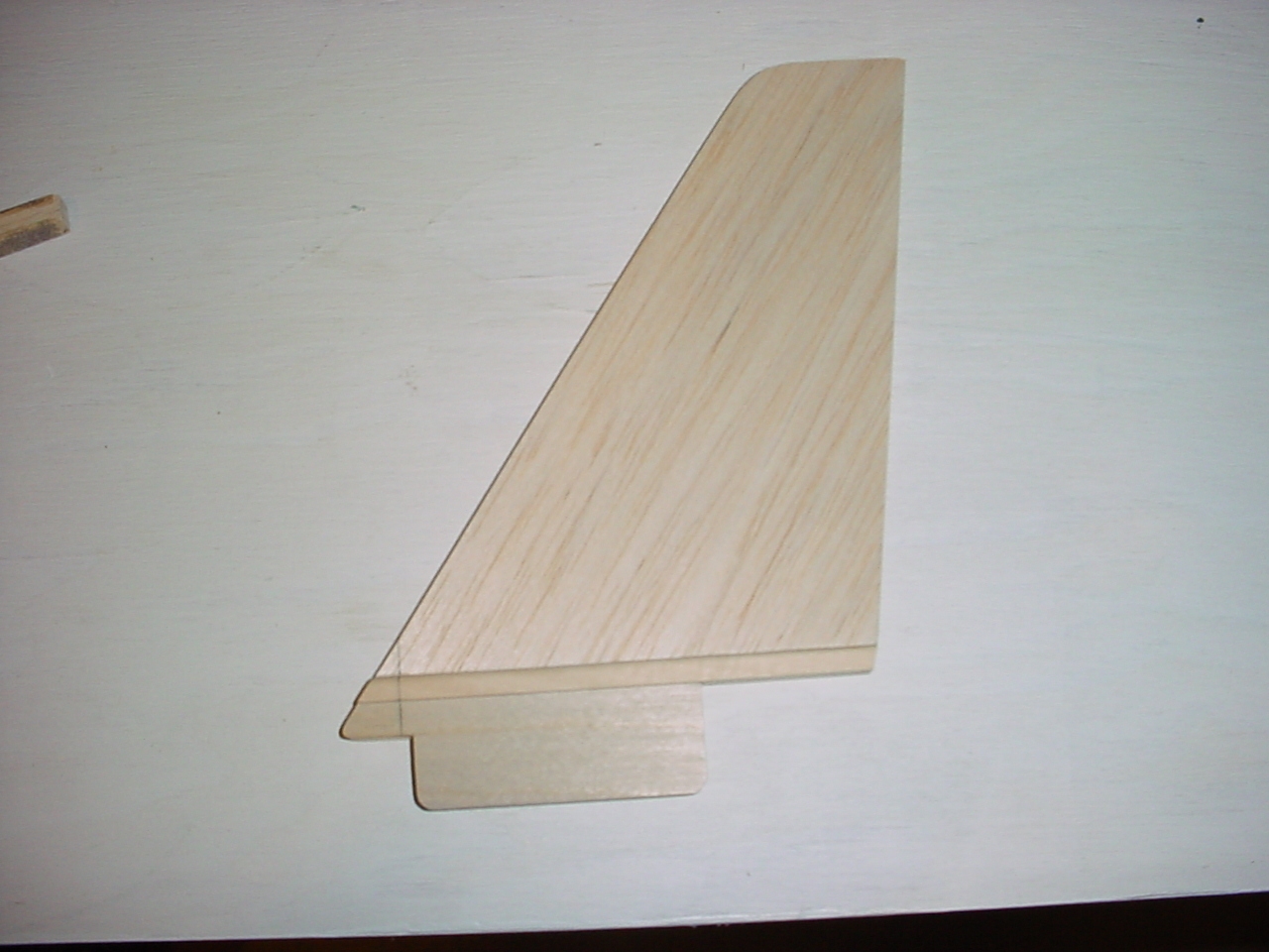 The next dilemma was what to do with the nose of the fin. Do I cut it square off and attach a hardwood nose
in its place? The design went through several iterations in my head, and actually several trials that
didn't make it into this log, but I eventually landed on something that worked.
The next dilemma was what to do with the nose of the fin. Do I cut it square off and attach a hardwood nose
in its place? The design went through several iterations in my head, and actually several trials that
didn't make it into this log, but I eventually landed on something that worked.
 This was absolutely the hardest part of this project so far...emotionally. I was so proud of the work I had
done on the fin - it was a beautiful, perfect piece of work. So it was very difficult to take a blade to it
and cut a piece off of it. This picture actually shows a second piece being cut off, as a smaller piece of
the same area was cut off to add some needed clearance over the face cap I placed over the fin slot in the
previous step.
This was absolutely the hardest part of this project so far...emotionally. I was so proud of the work I had
done on the fin - it was a beautiful, perfect piece of work. So it was very difficult to take a blade to it
and cut a piece off of it. This picture actually shows a second piece being cut off, as a smaller piece of
the same area was cut off to add some needed clearance over the face cap I placed over the fin slot in the
previous step.
 I couldn't be less pleased with my quality of workmanship, as I couldn't get the altered region sanded square,
and I gouged the wood a bit with the sandpaper. I also had only a working concept of the design in my head,
so the end vision wasn't clear. I only wish I had this design figured out in the very beginning, as this
would have made it very easy to make straight. But I was smart in cutting the new small hardwood pieces
oversize that you see in this picture, as this enabled me to sand them down to just where they needed to be.
If you click on the pictures to see the full size version, it will be easier to tell what you are looking
at. But now the nose of the fin actually kind of looks like a nose. Some filler and final sanding and the
finished product should look professional, though I feel like it was a bit of a salvage operation.
I couldn't be less pleased with my quality of workmanship, as I couldn't get the altered region sanded square,
and I gouged the wood a bit with the sandpaper. I also had only a working concept of the design in my head,
so the end vision wasn't clear. I only wish I had this design figured out in the very beginning, as this
would have made it very easy to make straight. But I was smart in cutting the new small hardwood pieces
oversize that you see in this picture, as this enabled me to sand them down to just where they needed to be.
If you click on the pictures to see the full size version, it will be easier to tell what you are looking
at. But now the nose of the fin actually kind of looks like a nose. Some filler and final sanding and the
finished product should look professional, though I feel like it was a bit of a salvage operation.
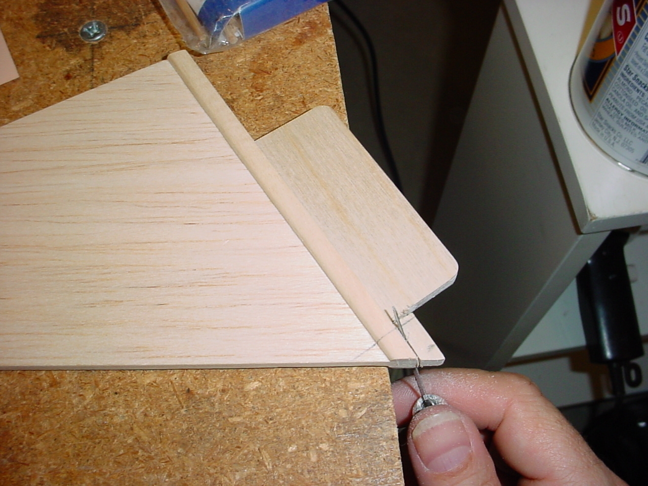
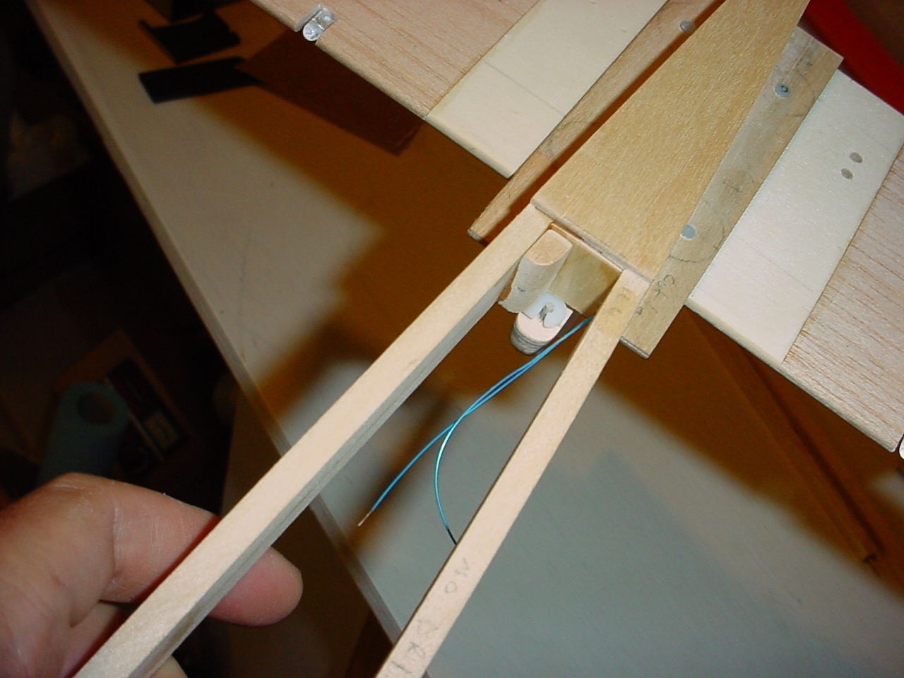
 This picture is a bit out of focus, but if you click on it, the larger version shows the metal pin that I
installed in the nose, and the Carl Goldberg flat hold-down that I attached to the tail boom below. The idea
is that when the fin is slid back into place, the metal pin will snap into the hold down which will prevent
the fin from sliding forward. Much work remains on the fin and tail boom to add the retaining pins that
will keep the fin in place (remember the two holes I drilled into the tail end a long, long time ago?). That
will come in the next step on another day. Also, the two wires you can see sticking out of the boom
will get a cap over them with access points for soldering as in the horizontal stabilizer. This is a backup
option for external lighting if the tail lights ever fail in the future.
This picture is a bit out of focus, but if you click on it, the larger version shows the metal pin that I
installed in the nose, and the Carl Goldberg flat hold-down that I attached to the tail boom below. The idea
is that when the fin is slid back into place, the metal pin will snap into the hold down which will prevent
the fin from sliding forward. Much work remains on the fin and tail boom to add the retaining pins that
will keep the fin in place (remember the two holes I drilled into the tail end a long, long time ago?). That
will come in the next step on another day. Also, the two wires you can see sticking out of the boom
will get a cap over them with access points for soldering as in the horizontal stabilizer. This is a backup
option for external lighting if the tail lights ever fail in the future.
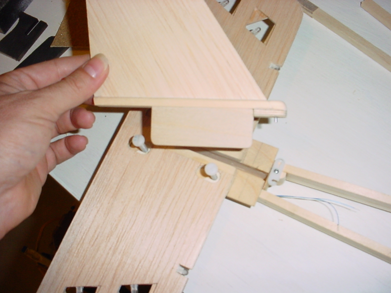
 Here is the assembly snapped into place. A perfect alignment! Just ignore the gap caused by the warp in the horizontal
stabilizer - I'll be working that out later.
Here is the assembly snapped into place. A perfect alignment! Just ignore the gap caused by the warp in the horizontal
stabilizer - I'll be working that out later.
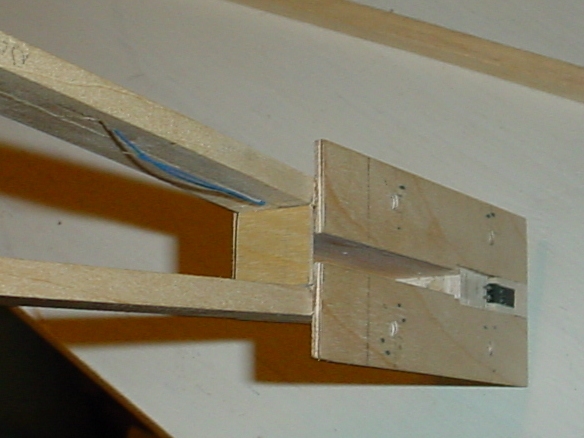
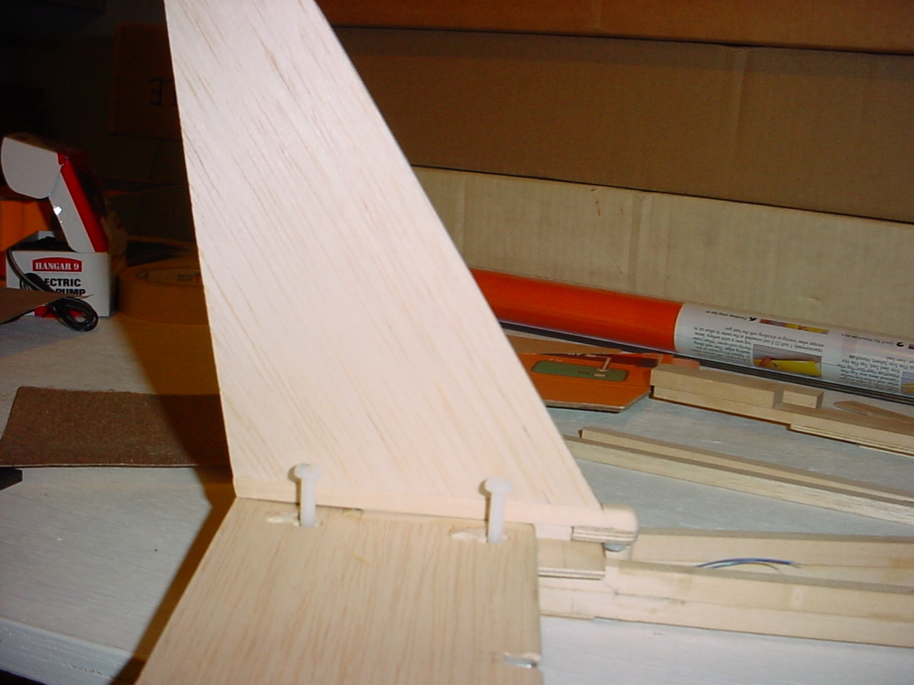
 And here's a view from underneath showing the pin engaged in the clip.
And that completes this session. Check back often, as I am currently on vacation and plan to spend at least a couple more days on this before I have to return to work, though perhaps not consecutively. Although, I am trying to remain engaged in the project, so will likely spend some time every day thinking about next steps. The clearer my vision, the better the end product.