TAIL SECTION
[10/07/2006]
Work continues on the tail boom, with a focus on the tail section. The tail is looking excellent, and I am very happy with the alignment and the tolerances. What you see here may not look like much, but this particular sequence spanned several hours, mostly due to the amount of sanding I had to do to get some things to fit just right. But every bit of progress is that much closer to completion, so I don't care if it takes me all day to do one little thing, as long as that one thing is done at the end of the day so I can move on to the next step.
 I needed to drill two pilot holes through the tail booms to accommodate locking pins that will be
installed later to secure the fin assembly (remember the first boom sticks I made that I had to scrap
because there were embedded wires in the way of where I wanted to drill?). There was only one problem
this time - I needed some way to ensure that I could drill the holes square through, perpendicular to the
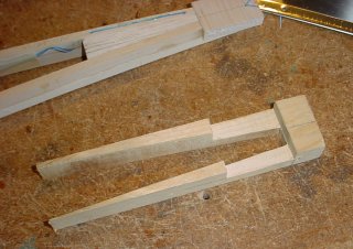
center line of the fuselage. My solution was to make a little jig. In about 10 minutes, I cut out a jig
on my band saw and was ready to roll (or drill as the case may be).
I needed to drill two pilot holes through the tail booms to accommodate locking pins that will be
installed later to secure the fin assembly (remember the first boom sticks I made that I had to scrap
because there were embedded wires in the way of where I wanted to drill?). There was only one problem
this time - I needed some way to ensure that I could drill the holes square through, perpendicular to the
center line of the fuselage. My solution was to make a little jig. In about 10 minutes, I cut out a jig
on my band saw and was ready to roll (or drill as the case may be).
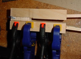
 Not bad for a ten-minute jig! The fuselage fit right in, nice and snug. I now had some square
corners and surfaces that I could use to support the tail boom in the drill press so the holes
would go exactly where I wanted them to go.
Not bad for a ten-minute jig! The fuselage fit right in, nice and snug. I now had some square
corners and surfaces that I could use to support the tail boom in the drill press so the holes
would go exactly where I wanted them to go.
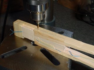 And here is the assembly in the drill press, just so you get the idea of how the jig worked.
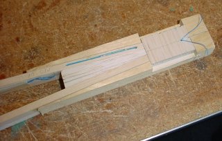
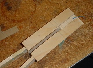
 And here is the tail boom removed from the jig to expose the two new pilot holes that I drilled.
They will come in handy, later, when I go to install the locking pins, as I may not have the option
to use a handy jig once more pieces (i.e. protrusions) are affixed to the frame. One of the holes
came through a little closer than I expected to the inner wires in the right-hand boom stick (I'm
not entirely sure how, but I must have been off on my measurements, somewhere), but it is not close
enough to be a problem, and the holes are right where I want them.
And here is the tail boom removed from the jig to expose the two new pilot holes that I drilled.
They will come in handy, later, when I go to install the locking pins, as I may not have the option
to use a handy jig once more pieces (i.e. protrusions) are affixed to the frame. One of the holes
came through a little closer than I expected to the inner wires in the right-hand boom stick (I'm
not entirely sure how, but I must have been off on my measurements, somewhere), but it is not close
enough to be a problem, and the holes are right where I want them.
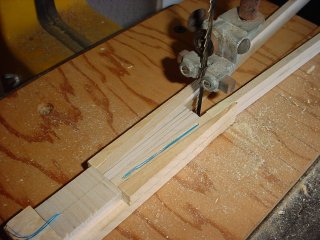 Once I had the pilot holes drilled where I wanted them, it was time to cut the slot for the fin tab into
the filler block that I installed last weekend. Remember I said most of it was coming out?
Well, here it is on the band saw, like Batman and Robin tied to a conveyor belt, ready to be sliced up.
Once I had the pilot holes drilled where I wanted them, it was time to cut the slot for the fin tab into
the filler block that I installed last weekend. Remember I said most of it was coming out?
Well, here it is on the band saw, like Batman and Robin tied to a conveyor belt, ready to be sliced up.
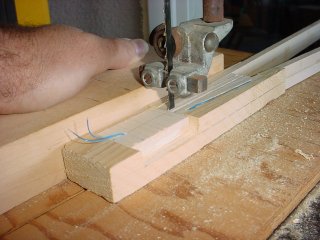 And here it is getting sliced up. I cut two slices to form the walls of the slot, then I dug out
the middle and sanded (and sanded and sanded) the slot to the desired width and tolerances. I must
say, it came out very nicely.
And here it is getting sliced up. I cut two slices to form the walls of the slot, then I dug out
the middle and sanded (and sanded and sanded) the slot to the desired width and tolerances. I must
say, it came out very nicely.
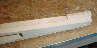
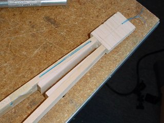 The completed task. After a considerable amount of sanding, the slot became a nice comfortable fit
for the fin - the descending tab slides right in. And if you look closely, you can see the holes down
in there.
The completed task. After a considerable amount of sanding, the slot became a nice comfortable fit
for the fin - the descending tab slides right in. And if you look closely, you can see the holes down
in there.
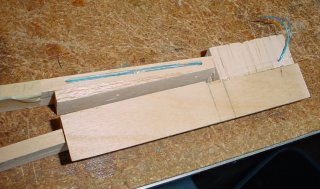 Here, I have assembled one half of the horizontal stabilizer mounting plate. The mounting plate was
originally one piece, with a slot in the middle (like the stabilizer), but the modification I made to
the design to support the electrical connectors required that I split this plate into two pieces. This
shot was taken after I sliced off all the epoxy boogers that oozed out between the cracks. I mixed up
a couple of good batches of epoxy today.
Here, I have assembled one half of the horizontal stabilizer mounting plate. The mounting plate was
originally one piece, with a slot in the middle (like the stabilizer), but the modification I made to
the design to support the electrical connectors required that I split this plate into two pieces. This
shot was taken after I sliced off all the epoxy boogers that oozed out between the cracks. I mixed up
a couple of good batches of epoxy today.
 Here is the second half of the mounting plate being permanently applied, epoxy boogers and all. The
epoxy was still very wet in this shot. Of course, that only lasted a few minutes, then I had to carefully
slice and dice the plastic-like epoxy boogers before they turned to stone. This half of the plate covers
the last of the exposed wires that run through the right-hand boom stick. I just need to add a connector
to the wires hanging out the back (in fact, I might do something radical and re-work the back end so there
are connection points to copper traces like I have in the stabilizer - I don't know why I didn't think of
that, earlier).
Here is the second half of the mounting plate being permanently applied, epoxy boogers and all. The
epoxy was still very wet in this shot. Of course, that only lasted a few minutes, then I had to carefully
slice and dice the plastic-like epoxy boogers before they turned to stone. This half of the plate covers
the last of the exposed wires that run through the right-hand boom stick. I just need to add a connector
to the wires hanging out the back (in fact, I might do something radical and re-work the back end so there
are connection points to copper traces like I have in the stabilizer - I don't know why I didn't think of
that, earlier).
 And here is the mounting plate, all cleaned up and ready for the next step. Actually, this picture was taken before it
was sanded down flat (being in two pieces, and the way it was clamped during assembly, it had a tendancy to
set up with a slightly bowed mounting surface - nothing a good amount of block sanding couldn't fix).
I don't remember if this is 1/8" or 3/32" plywood, but I'm sure I took it down at least 1/64". Not any
significant weight loss, but there is more considerable weight loss to come, yet.
And here is the mounting plate, all cleaned up and ready for the next step. Actually, this picture was taken before it
was sanded down flat (being in two pieces, and the way it was clamped during assembly, it had a tendancy to
set up with a slightly bowed mounting surface - nothing a good amount of block sanding couldn't fix).
I don't remember if this is 1/8" or 3/32" plywood, but I'm sure I took it down at least 1/64". Not any
significant weight loss, but there is more considerable weight loss to come, yet.
The next step is to define the next steps, as I have pretty much come to the end of my current checklist. I need to install the horizontal stabilizer mounting bolts (and figure out how to align the drilling guide I made back when I made the horizontal stabilizer), install the stationary fin locking pin and cut a hook into the fin tab, install the retractable locking pin and drill a corresponding hole in the fin tab, and cut out and glue a gusset to the bottom - not to mention install the locking pins.
It doesn't look like I will get to that this weekend, but hopefully next weekened (or even during the week, though I doubt it), but I may actually complete the entire tail boom assembly, including installing the rudder and elevator to the fin and stab, two weeks ahead of schedule! That's what I am shooting for. In fact, if I don't finish it next weekend, I will be lucky to get another chance to work on it before Halloween. I'm actually kind of worried that I won't get much done on the fuselage before the end of the year (you know how the holiday season can be - and I am NOT pushing anything this year, since I am really not up for another ear infection).
Keep your fingers crossed, and I'll keep you posted. It looks like there are potentially two other intervening household projects that might pre-empt further Questor progress, pushing my target completion date back, considerably. A third possibility is that we might move in the (too near) future, which would REALLY put a crimp on things.
Wish me good fortune!