TAIL BOOM, PART 1
[09/24/2006 - 09/25/2006]
I worked late into the night when I should have been doing homework, or sleeping (what an idea!), but I made some good progress on running the wires down the tail boom stick for providing power to the tail...for lights...for night flying.
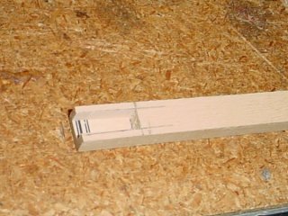 I cut a slot in the end of one 1/4"x3/8" stick which will eventually become the upper stick in a
laminate that will form the complete boom stick. This will be the right-hand boom stick and will
carry all the power for the tail (there will be no wires in the left boom stick). Anyway, I cut
out another piece of wood and glued it in as a floor piece to form a cradle for the connector
(installed later).
I cut a slot in the end of one 1/4"x3/8" stick which will eventually become the upper stick in a
laminate that will form the complete boom stick. This will be the right-hand boom stick and will
carry all the power for the tail (there will be no wires in the left boom stick). Anyway, I cut
out another piece of wood and glued it in as a floor piece to form a cradle for the connector
(installed later).
 I have a tiny end mill cutter that I got for my dremel rotary tool, but it works well in my drill
press, too. I stuck it in my drill press and used it to cut a pathway into the boom stick for the
wires to seat. This particular groove was cut on the outside edge of the boom stick, leading
away from the connector cradle.
I have a tiny end mill cutter that I got for my dremel rotary tool, but it works well in my drill
press, too. I stuck it in my drill press and used it to cut a pathway into the boom stick for the
wires to seat. This particular groove was cut on the outside edge of the boom stick, leading
away from the connector cradle.
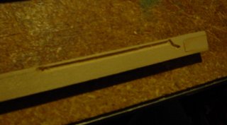
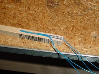
 From the end of the pathway there, a cockeyed hole was drilled through to the center of what will be
the bottom of this boom stick, and I cut a groove along the bottom (seen on top here) all the way
down to the tail end of the stick.
From the end of the pathway there, a cockeyed hole was drilled through to the center of what will be
the bottom of this boom stick, and I cut a groove along the bottom (seen on top here) all the way
down to the tail end of the stick.
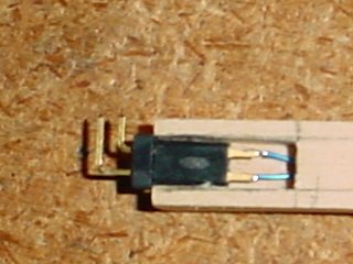 I installed a female connector into the cradle and ran some wires through the hole and soldered it up.
There is a male connector inserted into the female connector in this shot (electronic porn?), which
explains the two pins sticking up.
I installed a female connector into the cradle and ran some wires through the hole and soldered it up.
There is a male connector inserted into the female connector in this shot (electronic porn?), which
explains the two pins sticking up.
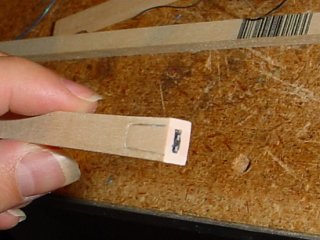
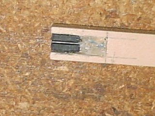 Here, I removed the male connector and flipped the female connector over and glued it into the cradle.
I then added some hot glue to stabilize and protect the wires where they attach to the connector.
Here, I removed the male connector and flipped the female connector over and glued it into the cradle.
I then added some hot glue to stabilize and protect the wires where they attach to the connector.
 The wires run through the groove on the back side of the cradle, then through the cockeyed hole and out
the bottom. The wires in this side groove are sealed in hot glue. It is important they be protected,
as this area will be somewhat vulnerable when the aircraft is disassembled. When assembled, they will be
protected by the fuselage wall.
The wires run through the groove on the back side of the cradle, then through the cockeyed hole and out
the bottom. The wires in this side groove are sealed in hot glue. It is important they be protected,
as this area will be somewhat vulnerable when the aircraft is disassembled. When assembled, they will be
protected by the fuselage wall.
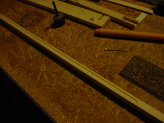
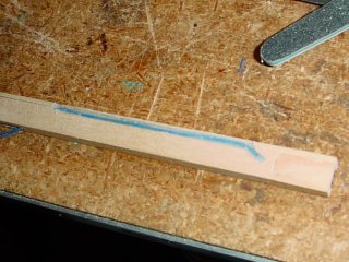
 And here are the wires tacked down with CA glue along the long path down the bottom side of the stick.
These wires will be completely encased in epoxy when this stick is laminated to what will become the lower
stick of the laminated pair.
And here are the wires tacked down with CA glue along the long path down the bottom side of the stick.
These wires will be completely encased in epoxy when this stick is laminated to what will become the lower
stick of the laminated pair.
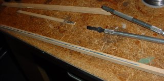
 Down near the tail, the wires pass through another hole and enter a groove along the top side of the stick
(where the horizontal stabilizer mounting plate will attach). I have run a pair of wires out through the
inside wall where I will install a couple of power access points, similar to how I made them in the horizontal
stabilizer.
Down near the tail, the wires pass through another hole and enter a groove along the top side of the stick
(where the horizontal stabilizer mounting plate will attach). I have run a pair of wires out through the
inside wall where I will install a couple of power access points, similar to how I made them in the horizontal
stabilizer.
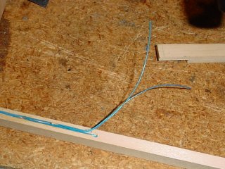
 At the tail end, I made a complete mess of things. I added another pair of wires and created two exit points.
This was based solely on confusion, and I do not know what I was thinking at the time, but I only really needed
one pair of wires coming out here. Perhaps I will fix this in a later step - or perhaps not. Following this
photo, I simply cut off the two wires I didn't need...but I'm not happy with the quality and am concerned about
any possible chafing hazard.
At the tail end, I made a complete mess of things. I added another pair of wires and created two exit points.
This was based solely on confusion, and I do not know what I was thinking at the time, but I only really needed
one pair of wires coming out here. Perhaps I will fix this in a later step - or perhaps not. Following this
photo, I simply cut off the two wires I didn't need...but I'm not happy with the quality and am concerned about
any possible chafing hazard.
 Back to the connector end, I cut out another small piece of basswood, glued it in place and sanded it flush,
thus completing the connector housing. The boom stick is basically ready for lamination.
Back to the connector end, I cut out another small piece of basswood, glued it in place and sanded it flush,
thus completing the connector housing. The boom stick is basically ready for lamination.