THE BEGINNING
[09/20/2006]
 This project began in the third week in August, 2006, and I started posting
about it on my personal blog a few days later.
It began with a prototype. I built a mock-up of the fuselage and some of the
tail pieces using cheap and readily available cardboard. From there, I made
a quick (and probably hasty) estimate of the wood I would need for the project,
and promptly ordered it.
This project began in the third week in August, 2006, and I started posting
about it on my personal blog a few days later.
It began with a prototype. I built a mock-up of the fuselage and some of the
tail pieces using cheap and readily available cardboard. From there, I made
a quick (and probably hasty) estimate of the wood I would need for the project,
and promptly ordered it.
 The wood arrived, yet I continued to unearth design considerations and was
revising my designs (for the tail) on a daily (sometimes hourly) basis. When
the project began, I had totally overlooked the night flying aspect and,
subsequently, failed to work the wiring considerations into the design. I
corrected that oversight, and then began building...but not without overlooking
a mechanical consideration or two and wound up having to start over due to
The wood arrived, yet I continued to unearth design considerations and was
revising my designs (for the tail) on a daily (sometimes hourly) basis. When
the project began, I had totally overlooked the night flying aspect and,
subsequently, failed to work the wiring considerations into the design. I
corrected that oversight, and then began building...but not without overlooking
a mechanical consideration or two and wound up having to start over due to
 a wire being in the path of where a hole was to be drilled.
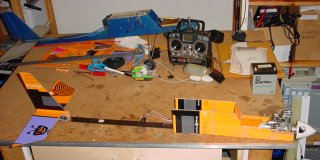
Since then, I have constructed a considerable portion of the horizontal and vertical stabilizers. The previous details are too many to mention, and many are captured in the archives of my personal blog if one wishes to examine them. It has been an interesting process thus far. Just as a brief re-cap, however, here are a few images to show the progress I have made up to this point:
 The tail boom consists, basically, of two main sticks. These sticks are each
constructed by laminating two 1/4x3/8" basswood sticks together.
The tail boom consists, basically, of two main sticks. These sticks are each
constructed by laminating two 1/4x3/8" basswood sticks together.
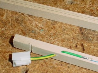 Because this aircraft will have opportunities to fly at night, it will have LEDs
installed in various places within the airframe. The tail requires six LEDs,
thus needs power, somehow. The power lines to the tail were run between the
laminated sticks, one conductor on each side.
Because this aircraft will have opportunities to fly at night, it will have LEDs
installed in various places within the airframe. The tail requires six LEDs,
thus needs power, somehow. The power lines to the tail were run between the
laminated sticks, one conductor on each side.
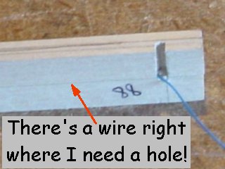
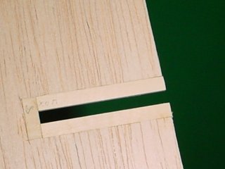
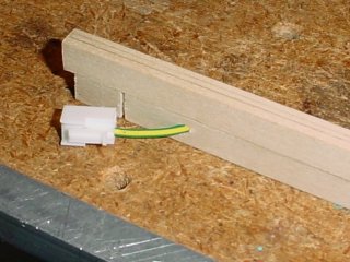 Here is one completed lamination, showing the connector that was to connect to
the fuselage. The tail boom will be removable from the fuselage, which is why
the connector is required.
Here is one completed lamination, showing the connector that was to connect to
the fuselage. The tail boom will be removable from the fuselage, which is why
the connector is required.
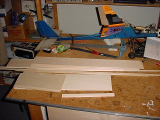
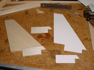 After I completed the tail boom main sticks, I realized I overlooked a routing
issue and wound up with two unusable main boom sticks, because there was a wire
right where I needed to drill a critical hole. I had to start over, but instead
of building new sticks, I moved on to other things. I cut out templates for the
vertical stabilizer (fin), and then proceeded to cut out the actual parts. Both
the parts and the templates are shown here.
After I completed the tail boom main sticks, I realized I overlooked a routing
issue and wound up with two unusable main boom sticks, because there was a wire
right where I needed to drill a critical hole. I had to start over, but instead
of building new sticks, I moved on to other things. I cut out templates for the
vertical stabilizer (fin), and then proceeded to cut out the actual parts. Both
the parts and the templates are shown here.
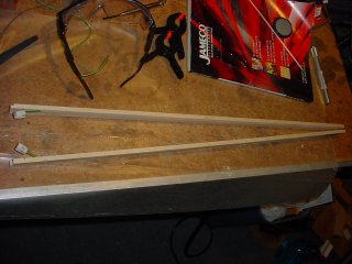
 I then got busy and cut out a whole slew of templates for various parts of the tail
section.
I then got busy and cut out a whole slew of templates for various parts of the tail
section.
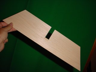 The horizontal stabilizer will consist of two layers of 3/32" wood, laminated together
to create a 3/16" thick stabilizer. I proceeded to cut out the upper layer out of
balsa wood.
The horizontal stabilizer will consist of two layers of 3/32" wood, laminated together
to create a 3/16" thick stabilizer. I proceeded to cut out the upper layer out of
balsa wood.
 I added some 3/4"x3/32" basswood strips in the slot where the removable fin will
slide through to reinforce the horizontal stabilizer in that area and make it more
durable.
I added some 3/4"x3/32" basswood strips in the slot where the removable fin will
slide through to reinforce the horizontal stabilizer in that area and make it more
durable.
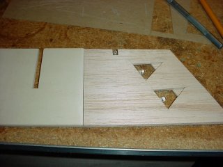
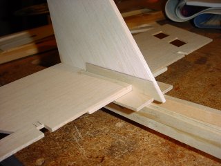 I cut out the base mounting plate, then staged the pieces together for a photo
shoot to get an idea how it will all fit together. The holes you see in the
horizontal stabilizer are for LEDs.
I cut out the base mounting plate, then staged the pieces together for a photo
shoot to get an idea how it will all fit together. The holes you see in the
horizontal stabilizer are for LEDs.
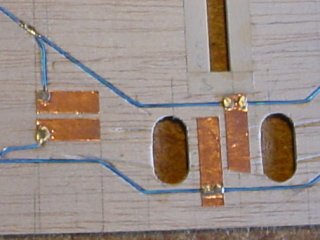
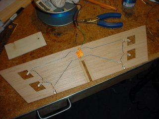 After a very lengthy LED selection process (to pick 27 LEDs that were very closely
matched, electrically) I installed six of them in the upper layer of the horizontal
stabilizer. I used an old dry ball point pen to carve out some tracks in the wood
for the tiny wires to run (using some very expensive wire wrap wire that I never
use). I also took some peel-and-stick thin copper foil (like for stained glass work)
and laid down a couple of tracks where I could solder some wires to. There will be
two small access holes in the stabilizer once it is all assembled so I can install
wires when needed. This is where the power will connect to the tail boom, though I
still haven't figured out how that will work, exactly, just yet.
After a very lengthy LED selection process (to pick 27 LEDs that were very closely
matched, electrically) I installed six of them in the upper layer of the horizontal
stabilizer. I used an old dry ball point pen to carve out some tracks in the wood
for the tiny wires to run (using some very expensive wire wrap wire that I never
use). I also took some peel-and-stick thin copper foil (like for stained glass work)
and laid down a couple of tracks where I could solder some wires to. There will be
two small access holes in the stabilizer once it is all assembled so I can install
wires when needed. This is where the power will connect to the tail boom, though I
still haven't figured out how that will work, exactly, just yet.
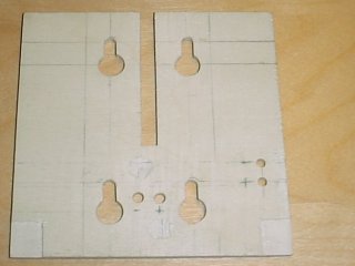
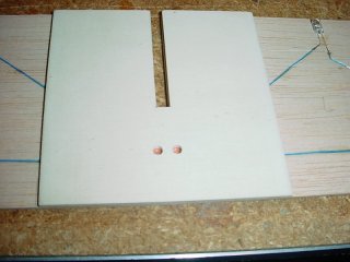 And here is a shot of the center section of the lower layer, which is cut from 1/8" light
plywood (making the center thicker than 3/16" after final assembly), with the two access
holes for the power traces.
And here is a shot of the center section of the lower layer, which is cut from 1/8" light
plywood (making the center thicker than 3/16" after final assembly), with the two access
holes for the power traces.
 Then I cut out the left and right lower layers out of 3/32" balsa. I cut triangular
holes in the bottom to contrast with the parallelgram cuts in the upper layer. When the
stabilizer is covered with MonoKote, I will be able to distinguish top from bottom
via these shapes to improve night time visual orientation.
Then I cut out the left and right lower layers out of 3/32" balsa. I cut triangular
holes in the bottom to contrast with the parallelgram cuts in the upper layer. When the
stabilizer is covered with MonoKote, I will be able to distinguish top from bottom
via these shapes to improve night time visual orientation.
The assembly is upside down here, so you're looking at the bottom.
 I added a couple more copper traces to give me more options, and drilled some more holes
to allow for the mounting bolts.
I added a couple more copper traces to give me more options, and drilled some more holes
to allow for the mounting bolts.
 I cut some more holes into the center mounting plate as well.
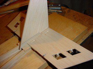
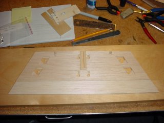 Another staged shot, showing how the entire assembly will look once it is all put together.
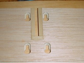 And here is a closer shot from the top side of what the mounting area looks like. There
will be four nylon bolts securely affixed to the base mounting plate on the end of the tail
boom. The stabilizer will [theoretically] slip right over the four mounting bolts and slide
back to lock into place. The fin will then slip in, extending down through the slot, and
provide a bit more holding power. The fin will be secured into place by two wooden pins
through the main boom sticks. Remember those holes I couldn't drill because a wire was in
the way? That's where the holes will be in the new sticks that I build.
And here is a closer shot from the top side of what the mounting area looks like. There
will be four nylon bolts securely affixed to the base mounting plate on the end of the tail
boom. The stabilizer will [theoretically] slip right over the four mounting bolts and slide
back to lock into place. The fin will then slip in, extending down through the slot, and
provide a bit more holding power. The fin will be secured into place by two wooden pins
through the main boom sticks. Remember those holes I couldn't drill because a wire was in
the way? That's where the holes will be in the new sticks that I build.
 [09/20/2006]
Another staged shot, showing the entire assembly as it stands as of this writing.
From this point forward, these project pages will track my progress as I forge ahead with this project. Keeping these records and making them public provides a sense of accountability that keeps me moving ahead. There will be periods where other life issues take priority and progress will slow or come to a complete stop for a while, but I am determined to see this through to the end. My goal is to complete the airframe and have it flying by June of 2007.